Difference between revisions of "CW Practice Oscillator Kit"
| Line 1: | Line 1: | ||
'''Code Practice Oscillator '''<br> | '''Code Practice Oscillator '''<br> | ||
| − | [[File:3D-CW-Code-Practice-Osc.PNG | | + | [[File:3D-CW-Code-Practice-Osc.PNG |450px ]] |
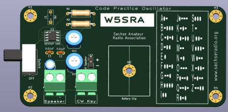
I decided to make a '''CW practice board for Morse Code training''' for my local HAM club. I have donated all 10 boards to the club. | I decided to make a '''CW practice board for Morse Code training''' for my local HAM club. I have donated all 10 boards to the club. | ||
| Line 14: | Line 14: | ||
This Kit comes with a 55mm Speaker that is connected '''LS2 (Version2 Bd)''' - '''J3 (Version1 Bd)''' and placed underneath the bottom of the PCB. | This Kit comes with a 55mm Speaker that is connected '''LS2 (Version2 Bd)''' - '''J3 (Version1 Bd)''' and placed underneath the bottom of the PCB. | ||
There is another speaker connector that uses a 5mm Terminal block with the label Speaker for larger speakers. | There is another speaker connector that uses a 5mm Terminal block with the label Speaker for larger speakers. | ||
| − | + | ---- | |
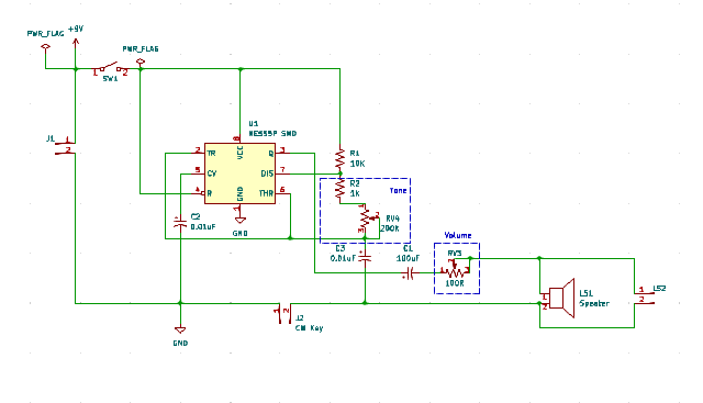
'''Code Practice Oscillator Schematic''' | '''Code Practice Oscillator Schematic''' | ||
[[ File:Code-Pratice-Schematic.PNG |700px ]] | [[ File:Code-Pratice-Schematic.PNG |700px ]] | ||
| − | + | ---- | |
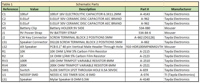
'''Code Practice Oscillator Schematic Parts''' <br> | '''Code Practice Oscillator Schematic Parts''' <br> | ||
[[ File:Code-Practice-Parts.PNG |700px]] | [[ File:Code-Practice-Parts.PNG |700px]] | ||
Revision as of 04:05, 23 February 2024
I decided to make a CW practice board for Morse Code training for my local HAM club. I have donated all 10 boards to the club.
It was a simple process to use KiCad 7.0 to design the board.
I am not going to explain how to use KiCad in this wiki page since I have other wiki pages explaining how to use KiCad.

This project uses a NE555 timer SMD SOIC-8 Chip that produces a square wave that can be adjusted between 300Hz and 1KHz
The power source is a 9Volt battery that is connected to J1 via a 9V BATTERY STRAP from Mouser Electronics.
This Kit was designed to be adjustable for the user to change to the tone to their preferred listening levels.
RV4 is a 200K ohm variable resistor that controls the tone between 300Hz to 1KHz.
RV3 is a 100 Ohm variable resistor that controls the volume.
The CW key is connected to a 5mm Terminal block that is label CW Key
This Kit comes with a 55mm Speaker that is connected LS2 (Version2 Bd) - J3 (Version1 Bd) and placed underneath the bottom of the PCB.
There is another speaker connector that uses a 5mm Terminal block with the label Speaker for larger speakers.
Code Practice Oscillator Schematic


