Difference between revisions of "CW Practice Oscillator Kit"
| (12 intermediate revisions by the same user not shown) | |||
| Line 1: | Line 1: | ||
| − | '''Code Practice Oscillator ''' <br> | + | '''Morse Code Practice Oscillator Kit ''' <br> |
| + | Code Practice Oscillator Kit | ||
| + | '''www.microrusty.com 2024''' | ||
| + | Version 1.0 | ||
| + | Sachse Amateur Radio Association | ||
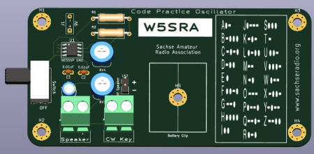
[[File:3D-CW-Code-Practice-Osc.PNG |450px |left ]] | [[File:3D-CW-Code-Practice-Osc.PNG |450px |left ]] | ||
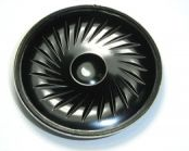
[[ File:Speaker-8-ohm-Mylar.PNG |250px | ]] <br> <br> | [[ File:Speaker-8-ohm-Mylar.PNG |250px | ]] <br> <br> | ||
| − | '''Microrusty.com 2024''' <br> | + | '''Microrusty.com 2024''' <br><br> |
| − | I decided to make a '''CW practice board for Morse Code training''' for my local HAM club. I have donated all | + | '''CW Practice Oscillator Kit Setup instructions''' |
| + | |||
| + | 1. Connect 9 volt battery to battery strap. | ||
| + | 2. Slide Battery into Battery clip holder. | ||
| + | 3. Connect Telegraph Key to the 5mm terminal block labeled '''CW Key'''. | ||
| + | 4. Slide power switch to '''On''' position. | ||
| + | |||
| + | '''Optional Speaker''' | ||
| + | 1. Disconnect the '''55mm 8-ohm 0.5 watt Speaker''' that is connected on the board at '''J3'''. | ||
| + | 2. Connect alternate speaker to the '''5mm Terminal block''' labeled '''Speaker'''. | ||
| + | |||
| + | |||
| + | |||
| + | |||
| + | I decided to make a '''CW practice board for Morse Code training''' for my local HAM club. I have donated all 8 boards to the club. | ||
It was a simple process to use KiCad 7.0 to design the board. | It was a simple process to use KiCad 7.0 to design the board. | ||
I am not going to explain how to use KiCad in this wiki page since I have other wiki pages explaining how to use KiCad.<br> | I am not going to explain how to use KiCad in this wiki page since I have other wiki pages explaining how to use KiCad.<br> | ||
| − | This | + | This kit uses a '''NE555 timer SMD SOIC-8 Chip''' that produces a square wave that can be adjusted between '''300Hz''' and '''1KHz''' |
| − | The power source is a | + | The power source is a '''9 Volt''' battery that is connected to '''J1''' via a 9V BATTERY STRAP. |
| − | This Kit was designed to be adjustable for the user to change | + | '''Tone and Volume Controls''' |
| − | RV4 is a 200K ohm variable resistor that controls the tone between | + | This Kit was designed to be adjustable for the user to change the tone and volume to their preferred listening levels. |
| − | RV3 is a 100 Ohm variable resistor that controls the volume. | + | '''RV4''' is a 200K ohm variable resistor that controls the '''tone''' between '''300 Hz''' to '''1 KHz'''. |
| + | '''RV3''' is a 100 Ohm variable resistor that controls the '''volume'''. | ||
| + | |||
The '''CW key''' is connected to a '''5mm Terminal block''' that is label '''CW Key''' | The '''CW key''' is connected to a '''5mm Terminal block''' that is label '''CW Key''' | ||
| − | This Kit comes with a | + | This Kit comes with a '''55mm 8-ohm 0.5 watt Speaker''' that is connected '''J3 ''' and placed underneath the bottom of the PCB. |
| − | There is another speaker connector that uses a 5mm Terminal block | + | There is another speaker connector that uses a '''5mm Terminal block''' that is labeled '''Speaker''' for larger speakers. |
---- | ---- | ||
'''Code Practice Oscillator Schematic''' | '''Code Practice Oscillator Schematic''' | ||
Latest revision as of 22:16, 5 March 2024
Morse Code Practice Oscillator Kit
Code Practice Oscillator Kit
   www.microrusty.com    2024
    Version 1.0
Sachse Amateur Radio Association
Microrusty.com 2024
CW Practice Oscillator Kit Setup instructions
1.	Connect 9 volt battery to battery strap.
2.	Slide Battery into Battery clip holder.
3.	Connect Telegraph Key to the 5mm terminal block labeled CW Key.
4.	Slide power switch to On position.
Optional Speaker
1.	Disconnect the 55mm 8-ohm 0.5 watt Speaker that is connected on the board at J3.
2.	Connect alternate speaker to the 5mm Terminal block labeled Speaker.
I decided to make a CW practice board for Morse Code training for my local HAM club. I have donated all 8 boards to the club.
It was a simple process to use KiCad 7.0 to design the board.
I am not going to explain how to use KiCad in this wiki page since I have other wiki pages explaining how to use KiCad.

This kit uses a NE555 timer SMD SOIC-8 Chip that produces a square wave that can be adjusted between 300Hz and 1KHz
The power source is a 9 Volt battery that is connected to J1 via a 9V BATTERY STRAP.
Tone and Volume Controls
This Kit was designed to be adjustable for the user to change the tone and volume to their preferred listening levels.
RV4 is a 200K ohm variable resistor that controls the tone between 300 Hz to  1 KHz.
RV3 is a 100 Ohm variable resistor that controls the volume.

The CW key is connected to a 5mm Terminal block that is label CW Key
This Kit comes with a 55mm 8-ohm 0.5 watt Speaker that is connected J3  and placed underneath the bottom of the PCB.
There is another speaker connector that uses a 5mm Terminal block that is labeled Speaker for larger speakers.
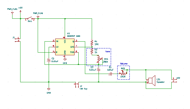
Code Practice Oscillator Schematic
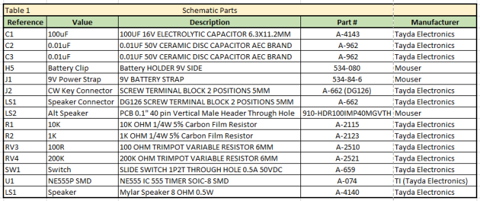
Code Practice Oscillator Schematic Parts


