Difference between revisions of "Installation and use"
(Created page with "'''Installation and setup'''<br> Connect a USB Micro B cable with power adapter to the wall plug you want to monitor.<\ Connect the USB Micro B cable from that adapter into...") |
|||
| (7 intermediate revisions by the same user not shown) | |||
| Line 1: | Line 1: | ||
'''Installation and setup'''<br> | '''Installation and setup'''<br> | ||
| − | Connect a USB Micro B cable with power adapter to the wall plug you want to monitor. | + | Connect a '''USB Micro B''' cable with '''power adapter''' to the wall plug you want to monitor. |
| − | Connect the USB Micro B cable from that adapter into J1 on the PCB board. | + | Connect the '''USB Micro B''' cable from that adapter into '''J1''' on the PCB board. |
| − | '''Note:''' This does not power the board microcontroller but will turn on the green LED on. | + | '''Note:''' This does not power the board or the microcontroller but will turn on the green LED. |
| + | [[File:MainPowerpic.png |350px]] | ||
| + | |||
| + | Connect a battery that uses a '''USB Micro B''' cable to '''J3''' on PCB Board. | ||
| + | This will power the board and start the monitoring process. | ||
| + | [[File:Batterypowerpic.png |350px]] | ||
| + | |||
| + | Insert and '''formatted SD''' card into the '''SD Card reader'''. | ||
| + | Press the '''reset button''' to start the monitoring process. | ||
| + | |||
| + | '''Optional:''' | ||
| + | Connect an optional '''RS232 interface''' for '''console port''' monitoring. | ||
| + | Connect '''USB A''' cable to plug on the '''PCB''' labeled '''Battery charger''' to charge battery while in use. | ||
| + | '''Note:''' Do not plug in a battery that has a charging circuit or states battery should not be charged while discharging. | ||
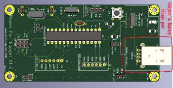
| + | [[File:Chargingpic.png|350px]] | ||
| + | ---- | ||
| + | ==[[ Power Fail Logger by Microrusty ]]== | ||
| + | ==[[Initializing the Microcontroller]]== | ||
| + | ==[[Setting Time and Date for the DS3231 RTC]]== | ||
| + | ==[[ Programming Power Fail Logger with Arduino IDE]]== | ||
| + | ==[[Installation and use]]== | ||
| + | ---- | ||
| + | ==[[ Main Page ]]== | ||
Latest revision as of 21:43, 17 August 2021
Installation and setup
Connect a USB Micro B cable with power adapter to the wall plug you want to monitor.
Connect the USB Micro B cable from that adapter into J1 on the PCB board.
Note: This does not power the board or the microcontroller but will turn on the green LED.
Connect a battery that uses a USB Micro B cable to J3 on PCB Board.
This will power the board and start the monitoring process.
Insert and formatted SD card into the SD Card reader.
Press the reset button to start the monitoring process.
Optional:
Connect an optional RS232 interface for console port monitoring.
Connect USB A cable to plug on the PCB labeled Battery charger to charge battery while in use.
Note: Do not plug in a battery that has a charging circuit or states battery should not be charged while discharging.


